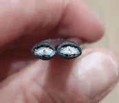
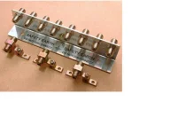
Right noted about the coupler fastenings, I just wondered. The cable is run as follows. Quad LNB 2 of which run to the living room, not used not connected. Other two go down side of an outbuilding, where the dish is mounted, then underground into the property passing under the floor of a room before arriving in the corner of what I call the tv room which is the first time I see the cable after it going underground. It starts off at the LNB as a very thick cable, thicker than WF100 but arrives at the tv room as a smaller cable looking like TX63 cable. Now where between the LNB and the tv room it changes I have no idea. The run from the LNB to the tv room is some 20m. There is then the additional run I have added of another 10m of TX63. This 10m run is only some 2m longer than it used to be before I changed the route of the cable and I never had breakup before. I did use a VU+ receiver before I managed to destroy it, 24v into it instead of 12v. I am quite happy to change the TX63 for WF100 if it helps. I could even go to WF125. I want to get this right as once finally installed the cable will be hidden behind a corner wall fascia glued and and non removable.
You say you inherited this arrangement so you have no knowledge of why a xx125 type cable was used. Was it used because of an abnormally long run was required or because the thicker cable can be buried, or both? This assumes that it is actually xx125 cable because if it isn't then all bets are off. Is there any indication on the outside of the cable about what it is. Often good quality cable has some identification marked every metre or so.
You can also lose signal at certain frequencies if the characteristic impedance is not maintained over the whole length of the cable. If for instance the hidden join between the thick and thin cables has been bodged you will have an impedance mis-match on that part of the cable. What can now happen if the length of the cable is changed (irrespective of the quality or attenuation of the extension cable) the reflections in the cable can change and maybe result in the changes you are seeing with picture breakup. Quoting a small section of the article on cables linked in post #11
"This isn’t the place to go into cable impedance, standing waves and what have you, but take my word for it, impedance bumps are a Bad Thing!"
I'm not suggesting that this is your problem but if it is spending money on a larger dish and LNB may not solve the problem. Investigating the cable join may be more productive. Don't forget a xx125 F plug will have different twist/clamp on diameter to suite the thicker cable.
Picture breakup and be caused by local electrical interference getting into the cable BUT usually as a result of using poor quality cable without 100% screening (cable such as the type D as in the cable article)
Is your new extension running parallel to any electrical cables and in close proximity? If so separate the cables.
Are there any wall plates in the path between the LNB and box? If so they should be fully screened.
Some notes on the difference between screened and unscreened wall plates
http://www.satcure.co.uk/tech/wallplates.htm
Satcure no longer trade.
Bear in mind that you probably don't want xx125 cable going to the back of your box. It is thick and stiff and doesn't hold a bend easily and is likely to put a strain on the F connectors at the back of your box. A xx125 cable would probably normally go to a wall plate and the box connects to the wall plate with a more flexible fly lead. The simplest of wall plates would just be a barrel connector